555 timer chip music player for the 2013 Ottawa Mini-Maker Faire
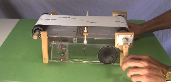
This is a music player I made for my entry for the 2013 Ottawa Mini-Maker Faire. It's based on the popular 555 timer chip.
My main design criteria was that it had to be far more robust than my previous music player that used pencil marks for the resistors. Those pencil marks wore away from the paper moving over them and taking away the pencil lead.
It was an overwhelming success, basically going through 14 hours of almost constant play at the Maker Faire, not to mention being cranked vigorously by countless kids (though I did have to repair the crank early on.)
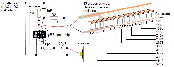
Below is the electrical circuit making use of the 555 timer chip.
How it works
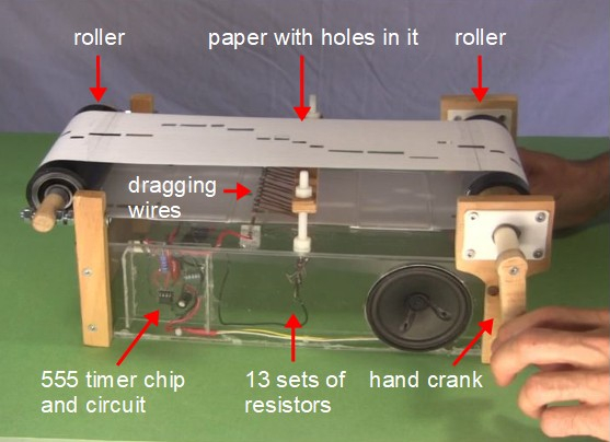
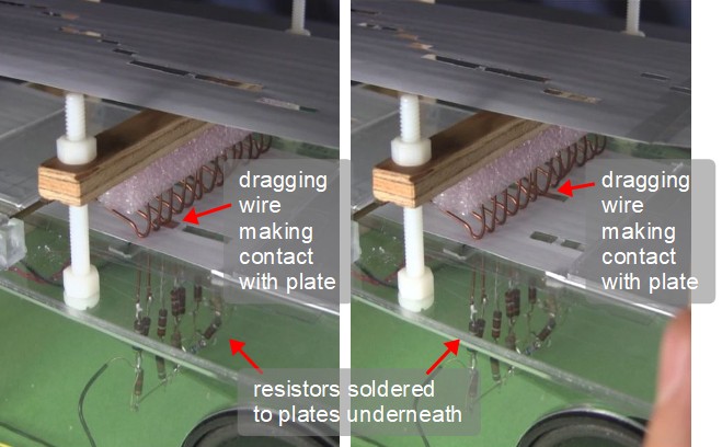
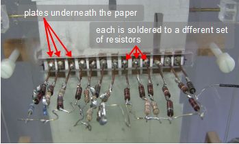
Looking at the photo on the left below, a continuous piece of paper is rolled around and around the two rollers by turning the hand crank. That piece of paper has holes in it, repesenting a song (Scarborough Fair in this case.) As shown in the photos on the right, the paper is dragged between the dragging wires that are above the paper and the copper plates that are below the paper. When a hole is between, the dragging wire makes electrical contact with the plate and a circuit is closed. The electricity takes the path through the resistor(s) soldered to the bottom of that plate (see 4th photo below.)
Referring to the circuit diagram above, to make the sound, the 555 timer chip sends different frequencies, or music notes, to the speaker. In this case there are 13 possible frequencies. The frequencies are determined by capacitor C1, resistor R2 and one of the 13 sets of resistors that are part of the "dragging wire, plates and sets of resistors" shown on the right in the circuit diagram.
The values of C1 and R2 don't change. What does change is which of the 13 resistor sets electricity is going through at any time. It can be only one of them at a time. And as pointed out in the first paragraph above, that's determined by which which dragging wire and plate have a hole between them. In the diagram above, for an example, the path through the 4th set of resistors above which is 4313 ohms, musical note D3, has been highlighted.
Turning the crank moves the paper along, the holes allowing different dragging wires and plates to make contact, changing the resistance at pin 6 of the 555 timer chip. That results in the chip sending different frequencies, or musical notes, to the speaker.
How the resistors were selected
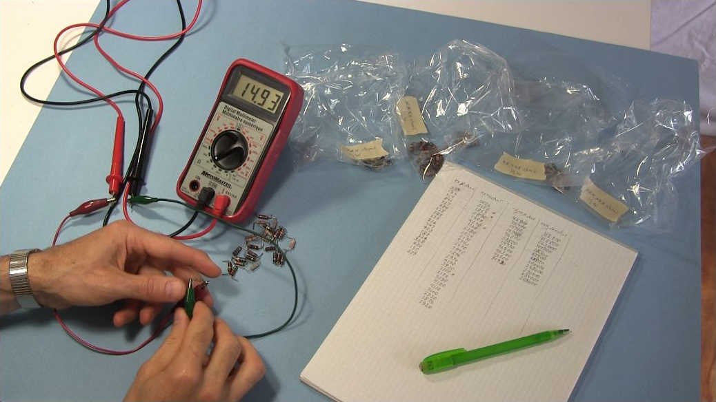
The values for the resistors were driven by two things. The first was that I had a bag of miscellaneous old resistors I'd bought at an electronics reuse store and this was a perfect opportunity to finally make use of them. The second was the formula for the resistances for the 555 timer chip circuit to get the desired frequencies. I originally got the formula from wikipedia's page for the 555 timer chip but it solved for the frequency. A little algebra allowed me to solve for an amount of resistance to add to R2, i.e. the resistance for each set of resistors soldered under the plates.
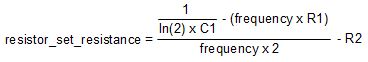
The frequencies themselves came from a table of piano key notes and corresponding frequencies I'd found online. Plugging the formula into the spreadsheet below, I was able to play around with the capacitance of C1 and the resistance of R2 until I had resistances that were spaced well enough apart to account for error while still being in the range of what I had in my bag of old resistors.
Here is the spreadsheet I used, given here in case you want to make one. I've given it in two different formats in case one format doesn't work for you.
- 555_music_player_resistances_mf.xls - in .XLS format for Microsoft Excel (for example)
- 555_music_player_resistances_mf.ods - in .ODS format for OpenOffice (for example)
Video - 555 Timer Chip Music Player for Maker Faire
Here's a video I made that shows how it works and then shows some of the construction details.
