Table of Contents
The parts to be installed (on page 1)
Figuring out where to put things and mounting the inverter, E-Panel and charge controller (on page 1)
Wiring the solar panels and running the cable into the E-Panel (on page 2)
The AC wiring and making a 240VAC outlet work with a 120VAC inverter (on page 3)
Wiring the Outback turbo fan for sealed inverters (on page 3)
The battery bank, battery temperature sensor and venting (on page 3)
Powering DC Loads (on page 4)
Controlling and monitoring - Outback Mate (on page 4)
Powering DC loads
All the lights, the slide out portions of the bedroom and living room and a few other
loads were formerly powered by the small battery in the small battery compartment.
This battery was removed and the new 900AHr battery bank was used instead.
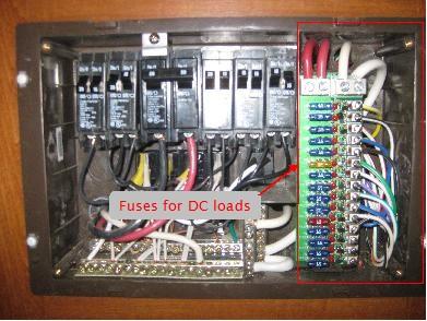
Breaker panel with section for DC loads.
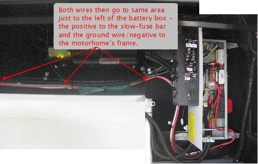
A 4AWG wire for the positive DC side was already run all the way from the
breaker panel to the front storage compartment where it was connected to
a slow-fuse bar. So all that was necessary was to run a 4AWG wire from
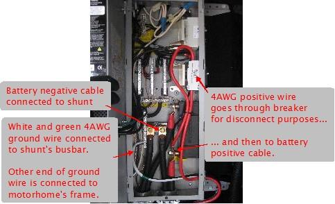
where the positive battery cable was connected in the E-Panel
to the slow-fuse bar (see photos below.)
The negative side of the DC was done through the motorhome's
frame. There was no actual wire running from the battery to the breaker
panel for the negative. For grounding purposes, I'd already already run
a white and green 4AWG from the motorhome's frame to the E-Panel's shunt
busbar and from there to the ground bar. The battery negative cable was
connected to the shunt so nothing extra had to be done for the negative side.
The battery negative terminal was already connected via suitably thick wires
to the motorhome's frame.
Wiring for DC loads in the E-Panel.
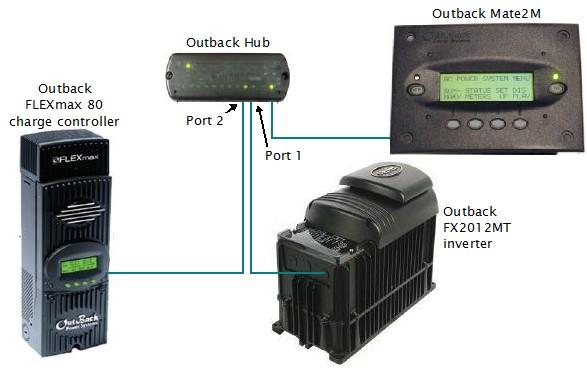
Controlling and monitoring - Outback Mate
The Mate controls and monitors the inverter and charge controller through
the hub, though the charge controller can also be accessed from its own front panel.
Here's how they are all wired together. The inverter must be connected to
port 1 and the charge controller to port 2. The Mate is connected to a
specially marked port called 1st MATE.
Mate controlling components through the Hub.
The final step was to mount the Outback Mate to the exterior of a closet wall
in the living area and run a CAT5e cable from the Outback Hub to the Mate.
The cable that came with the Mate wasn't long enough so I went to a
local consumer electronics store and bought a 50 foot long straight through
CAT5e cable (i.e. not a crossover cable) with RJ-45 connectors on the ends.
This worked just fine.