EGENS HHO Electrolyzer
The following is an efficient HHO generator/electroyzer generaously shared by its creator, Ray. The first part of this details the EGEN but make sure to read the second part too where Ray gives the story of its development from inception to where it is thus far. Ray is making this open source as of 2026.
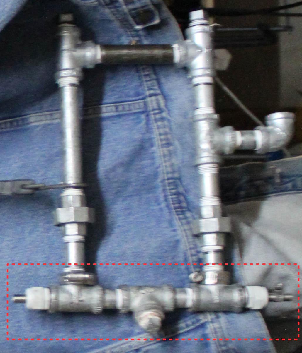
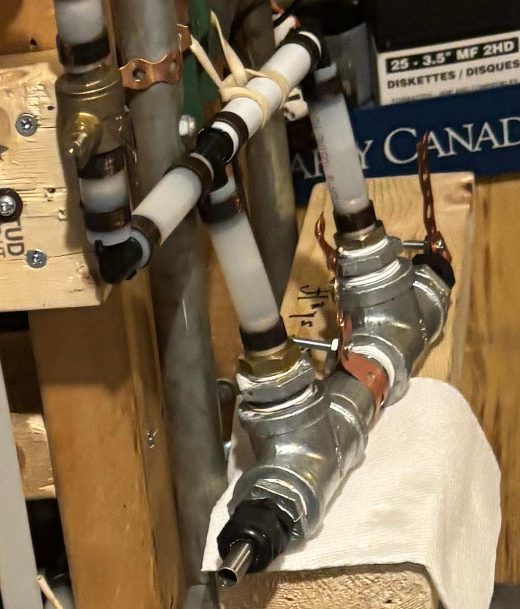
Below are two photos of the EGEN by itself, not connected to a power source. The second photo, the angle view, is taken from one of the photos further below of a test stand where there are additional EGENs that are connected electrically.
The outer electrolyzer electrode is made up for piping composed of galvanzied steel tees and a nipple and the inner electrode is a stainless steel tube or rod. The whole is designed to handle above atmospheric pressure.
The following is Ray's detailed write-up. Our thanks to him for sharing this with us.
What is an EGEN?
It is simply an arrangement of pipe fittings, isolators that support an electrode in the exact centre of the pipe fittings. It is used as an electrolyzer to separate hydrogen and oxygen into gases from water.
The research is based on low pressure (less than one PSI) and also high pressure (34 PSI). The unit itself is named an EGEN, where "GEN" refers to a gas generator. The pressure is dependent on the amount of voltage applied. He has built 13 EGENs of varying sizes and materials, 304 SS, galvanized steel pipe from 1/2 inch pipe fitting to 2 inch pipe. The EGENs can be used under any appliance, currently testing two different units. He has not yet found the top end pressure, more testing is needed.
The electrolysis occurs all along the EGEN from tee to tee, the teflon must be on the threads because without it the threads would gall together. The teflon tape at the beginning of the nipple is joined electrically because the threads are touching, the tape acts as a lubricant to reduce the friction in the fittings. There's minimal use of teflon tape on all threads and continuity is always checked for. Any other lubricant would transfer into the electrolyte. Teflon grease lubricant could have been used but it ends up in the electrolyte.
To build it go to Home Depot, Home Hardware, or any plumbing shop.
Test stand
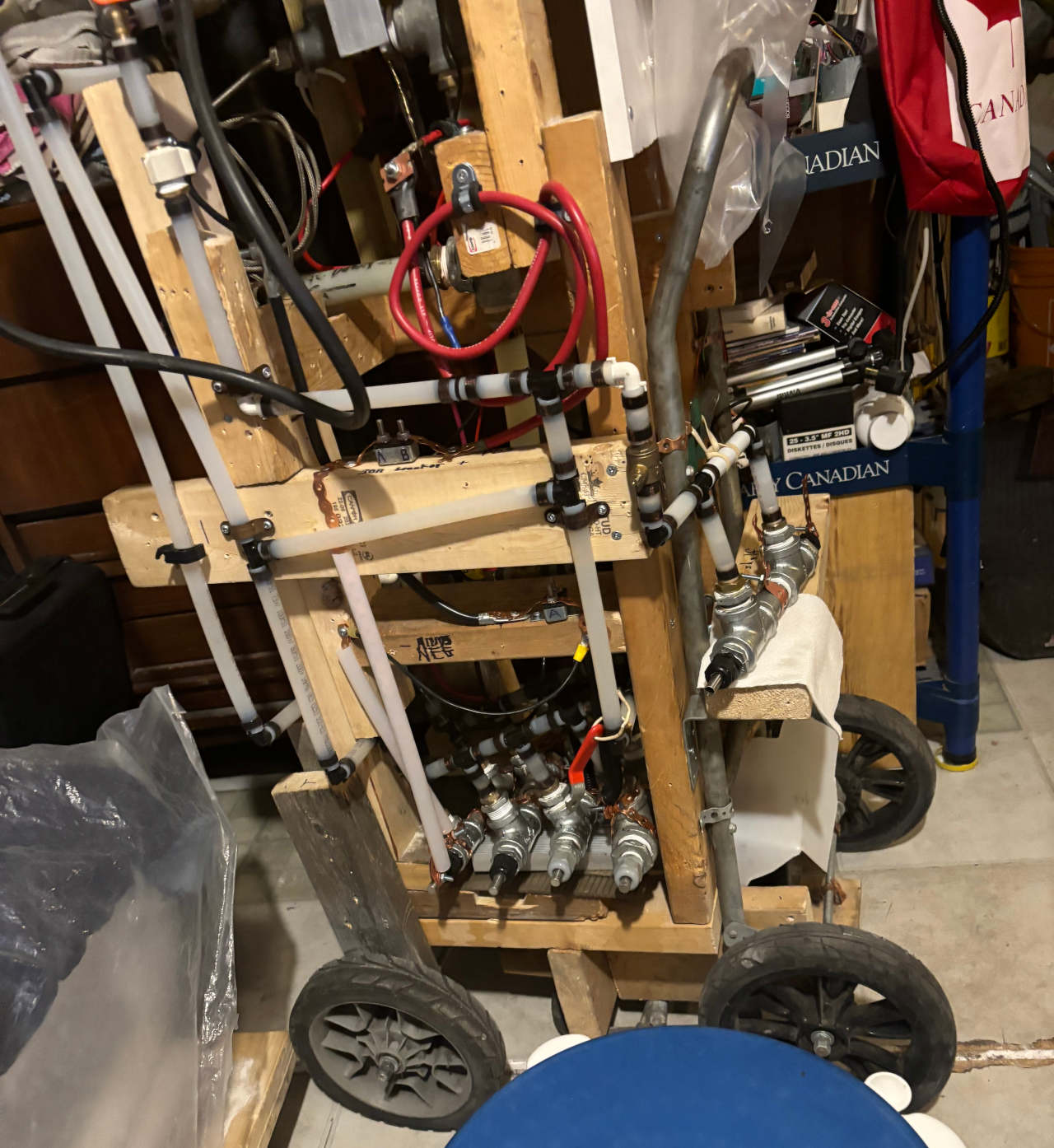
The following are two views (left and right) of a test stand making use of multiple EGENs. The first photo shows 4 EGENs connected in parallel and mounted inside the bottom of the test stand. They did not perform very well with a pressure under 2 PSI. A 5th EGEN is mounted on the side of the test stand.
The following is a photo of the opposite side of the test stand with the EGENs removed.
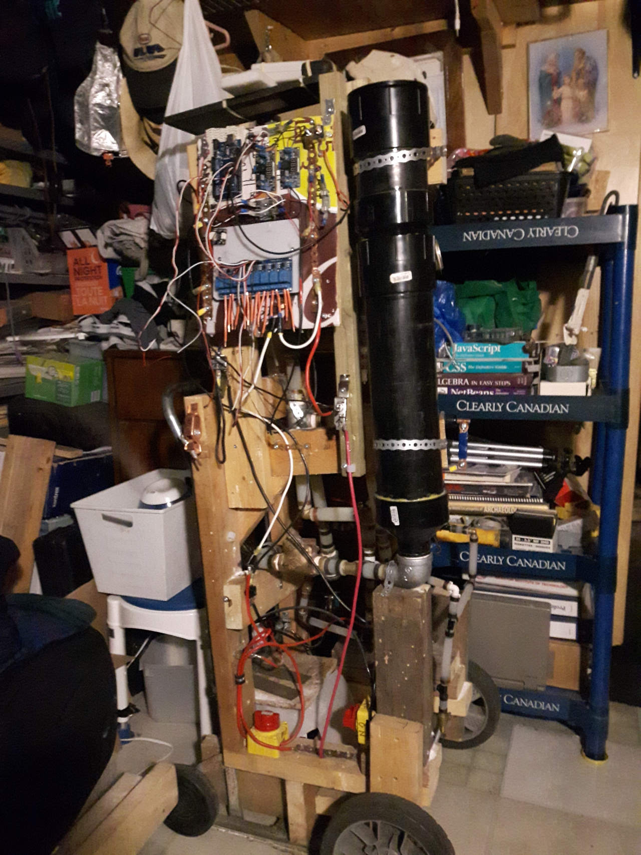
Ray has since built a stand on a Canadian Tire rolling wagon.
Another test setup
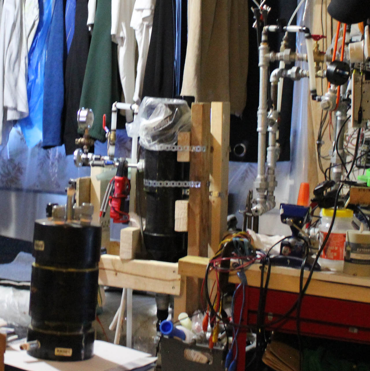
Here is another test setup in a location convenient for hanging components from above.
Making an EGEN
The following diagram shows the basic parts of an EGEN flooded reactor as of August 21, 2024. It depicts a 3/4" steel pipe and fittings. The 1/2", 3/4" and 1" designs have all been tested with up to 24 volts DC. Larger sizes in the future will generate more capacity.
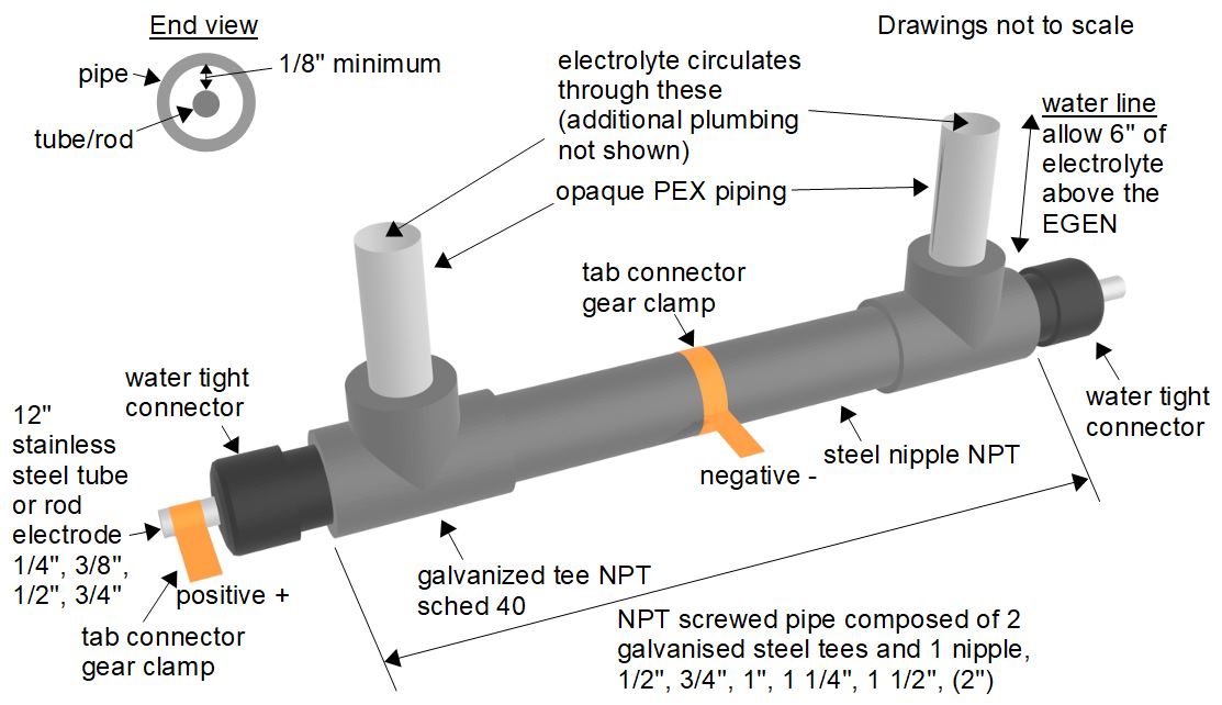
For the tube or rod electrode, stainless steel has the least corrosion factor. The water tight connector centers the tube/rod in the piping. The water tight connector can be plastic or metal, though if they're metal then there must not be electrical conductivity between the tube/rod and the piping. There should be a minimum of 1/8" between the outer surface of the tube/rod and inner surface of the piping to prevent electrical shorts.
The electrolyte mix is 1/8 tsp baking soda per 250 ml distilled water.
The power supply used was 24 volt, 30 amp variable. Use 6 volts, 1.8 amps DC across the tab connectors for 3/4" pipe fittings. 6 volts will generate about 16 PSI. 16 PSI x 3.14 x 0.5 inches x 0.5 inches (pi x pipe radius squared) = 12.56 GPM. 12.56 GPM x 3.78541 = 47.54 litres per minute (1 GPM = 3.78541 litres per minute). A V8 engine needs 350 CFM to run, air and fuel.
BOM - Bill of Materials
This is a bill of materials for the EGEN and the parts that go with it. For example, it lists three 1/2 inch galvanized NPT tees where two of them are on the electrolyzer itself as in the above diagram, and a third is for attaching a fill tank for testing. If the EGEN is used with what Ray calls a hi-lo setup, it fills the EGEN by gravity. This is the new design for test module #2. It is built, just waiting for Ray to finish the electrical circuit.
- three - 1/2 inch galvanized NPT tees
- one - 1/2 inch X 5 inch galvanized nipple NPT
- two -1/2 inch NPT water tight connector they are plastic or aluminum, or SS, are used to secure a 1/2
- inch round electrical cable to conduit box usually outside in wet conditions.
- two- 1/2 inch X 6 inch galvanized NPT nipples,
- two -1/2 inch galvanized NPT unions
- two- 1/2 inch X 2 1/2 inch Galvanized nipples
- one- 3/8 inch solid SS rod or 3/8 inch SS tube X 12 inches long
- two -gear clamps 1/2 and a 1 inch
- Distilled water, drinking water has to many impurities
Other notes
- Galvanized fittings are used in older drinking water systems due to less corrosion.
- Do not use copper pipe because it can cause chlorine gas when exposed to dc power in using salt in electrolyte.
- Stainless steel 304 or 316 NPT fittings may be used.
- Standard malleable steel pipe NPT may be used, although the corrosion factor is very high.
- PEX opaque piping can be used above the 1/2" tees to view the reaction with PEX X NPT adapter instead of steel pipe PEX pipe is rated about 100 PSI burst pressure.
Many things can be built using the EGEN, BBQ, outside boiler, outside warm air heater, outside stove, can be adapted to any vehicle older models. Lawn mover, rototiller. Check with your insurance company first.
A little history building the HHO test stands (September 2026)
My first ATM electrolyzer build took about 4 1/2 years to build. It was started on a suitcase wheeler that was found in the garbage. I added wood pieces to carry the battery, some electronics, an Arduino Nano, and a 3 imp. gallon ABS tank to carry the electrolyte. The ignition portion was built from 2 inch galvanized steel pipe with a spark plug added to the top. For ignition, I used a 12 volt coil which was controlled with 30 amp 12 volt relays for length of spark. There were a couple of buck converters to power the Nano and some 5 volt relays. From the internet, I found a circuit built by a race car builder to send fire down the pipes while he was driving. His design used three auto relays, I changed it to use only two relays (30 amp). The electrolyte level was close to six inches from the top, the length of the ignition module was close to 12 inches. At that point I installed pex pipe which was around 24 inches in length. The pex pipe allows you to observe the reaction in the fire tube riser stand. At the bottom, two pex 90 degree were installed rising back up into the bottom of a 4 inch ABS pipe water tank with an air gap on top. In the upper portion of the fire riser, a pex tee was installed. This is where the gas supply enters. The gas generator took at least 3 or 4 years to figure out the best method. The tank type was tried, it generated some but not enough, because the electrodes were too far apart. Ideally they should be at least 1/8 inch or 3 mm apart.
These generators are under the electrolyte to discourage flashbacks that are common with other designs. To measure the HHO gas pressure a manometer is used. For up to 2 PSI, a hand manometer was used. Above 2 PSI, digital manometers were used but only up to 14.6 PSI, after which it fails with ERR. For above 14.6 PSI, analogue gauges were used and therefore those were what were used to measure the 34 PSI which the 2 inch EGEN develops. This is not the top end; it will go higher and these tests are done outside.
What is the point of a 34 PSI HHO? Well you could use it on a Cracking furnace at the refinery, although those Cracking furnaces use much higher gas, closer to 100 PSI. Most high-pressure steam boilers run 1 to 5 PSI gas pressure natural gas.
When assembling the generator, use minimal Teflon tape, one to one and a half wraps is plenty. The tape itself does not seal the joint, it is the tightness of the screwed fittings which does that. Do not use pipe dope because it will foul the electrolyte.
In 2023, I awoke with a new design (EGEN) in my head. Using an electrode inside of a pipe fitting with isolators on the end. Hitting it with 4 volts DC, it generated close to 1/2 lbs of pressure, raising it up to 9 volts, it generated close to 8 PSI. Now I knew that this was the way to go.
With the help of a friend we took it outside. He ran the video camera (canon). Myself, I still wasn't to sure what it might do. Wearing a face shield, I fired up the two switches. It made a loud clicking sound and shook the machine on one side. This lasted for 1 or 2 seconds. There was something wrong with the camera, that is all it recorded. It was enough to realize that it would be safe in the house. When firing the machine, a red orange flame shot down through the electrolyte firing riser. I tested it many more times, impulse 200 PSI pressure gauge was ruined.
Originally I had hoped that the ignition pressure would push the electrolyte back up to the storage tank. There was pressure alright but from the EGEN themselves. The machine is close to five feet high, so approximately 5' X .434 = 2.17 PSI was being developed from the EGEN. This was the cause that brought the electrolyte back to the tank.
More research is needed into the EGEN design. So far I have built 13 different EGENs. As each one was built the PSI and DC power were recorded and the temperature as well as the TDS of the electrolyte. The smallest one was a 1/2 inch design using galvanized fittings and a 3/8 SS 304 solid electrode.
The largest one was built with 2 inch 316 SS fittings, 1/2 X 20 inch 304 SS electrode tube, sched 40. It generated 34 psi of HHO. The top-end PSI has not been reached. This could only be used on industrial applications, cracking furnaces, large steam boilers, water treater.
Some older electrolyzers
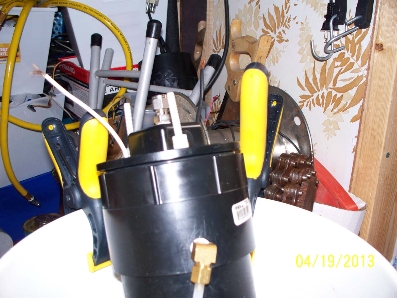
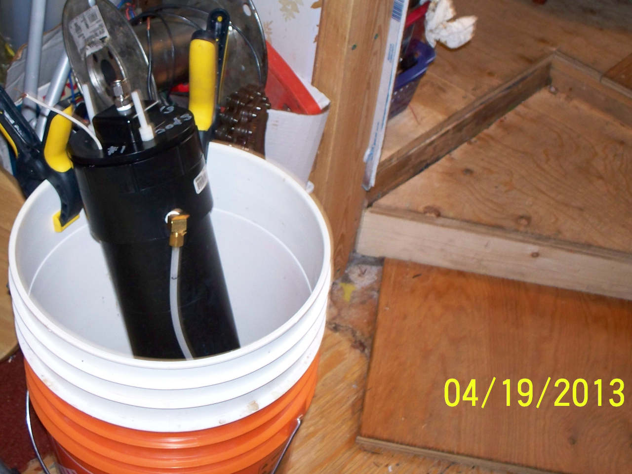
The following are some older designs. Neither of these designs produced much HHO, so they are in the bucket. After this the tank type reactor with SS rods was designed.
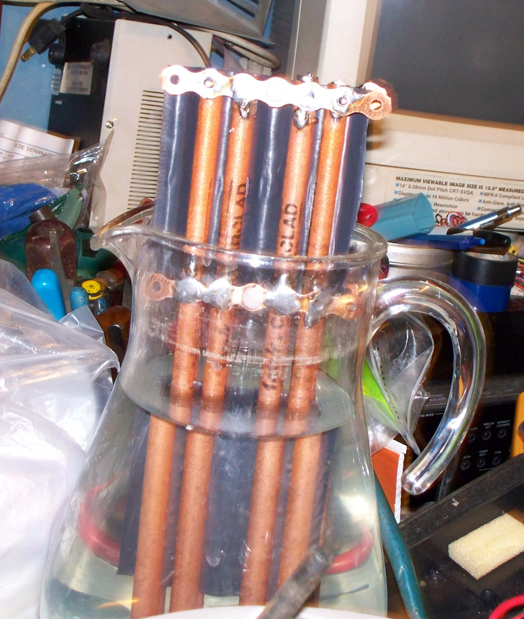
The following uses 1/8 inch rods separated with corrugated plastic between the + and the - elements, using nylon bolts to hold everything together.
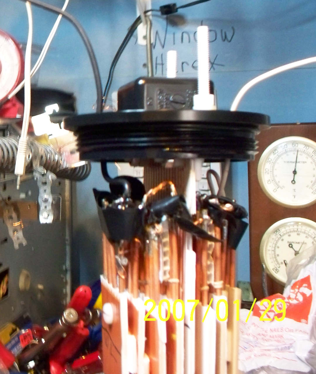
The following uses 3/8 inch brazing rod soldered together in two separate elements with corrugated plastic using nylons bolts between the + and -.
|
Do you have a project you'd like to share on rimstar.org too? You're more than welcome to. Click here for details. |
|

