These are attempts to replicate the Linden Experiment
and figure out if the horseshoe magnets used in the testatika in general are
tapping an energy source. In this case I wanted pulsed the magnets with
high voltage DC spikes from my small Van de Graaff machine.
A side result of this was that I found I was able to convert
high voltage spikes to low voltage DC very easily, something that
everyone seems to think is a difficult thing to do.
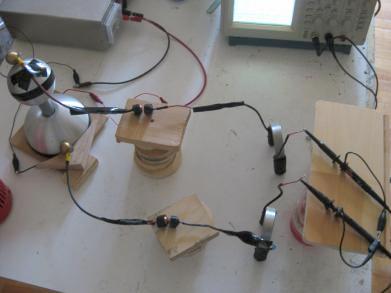
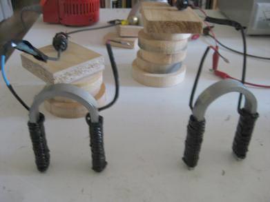
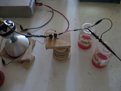
Pulsing with two magnets
I first wired up two magnets as closely as I could to what is done in
the 3kW testatika machine. Note that the ends of the coil wires at the bottom
are not in electrical contact with anything. Their lower ends are simply
insulated. The wires have a layer of heat shrink tube followed by a layer of
black electrical tape so the turns are spaced apart giving some capacitance.
The lower spark gap in the photo above is closed, there is no gap. So the only
gap is in the upper spark gap. If I open the lower spark gap then I got very little
pulsing on the lower magnet.
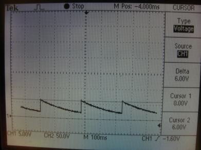
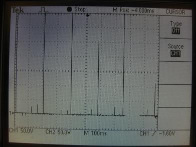
Spikes for lower magnet, measured relative to ground.
 |
|
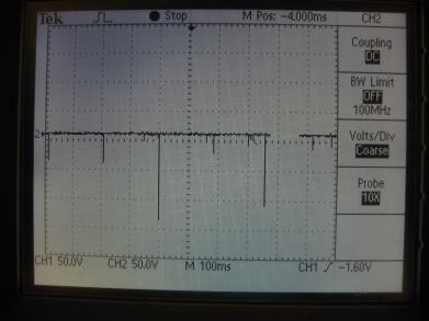
Spikes for upper magnet, measured relative to ground.
 |
|
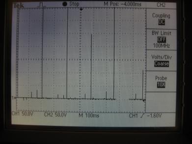
Spikes measured from one magnet to the other (using the
math operation of the oscilloscope.)
 |
|
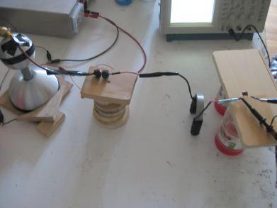
Pulsing one magnet, converting high voltage spikes to low voltage DC
Since in the above test I didn't use a spark gap for the lower magnet,
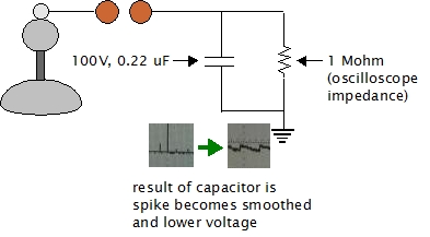
I figured I didn't need it. So I used just one magnet. Then, to convert
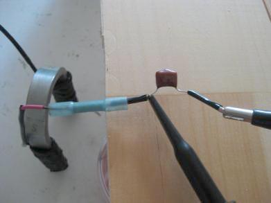
the spikes to low voltage DC I inserted a 100V, 0.22 microfarad capacitor as shown
in the photos below. The capacitor's left lead goes to the coil and the
scope probe, and its right lead goes to ground. I set the probe
attenuation to 1X.
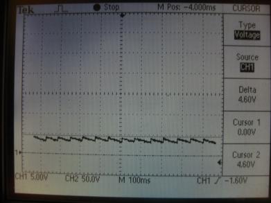
From the above scope shots you can see the spikes are well over 300V but
their duration is so short that I figured the capacitor could handle it.
The above circuit should be familiar to anyone who's made AC to DC power supplies.
It's simply the capacitor that's usually added in parallel just after the full wave
bridge rectifier. To select the capacitor, I first noticed that the spikes on
the scope were about 200ms apart. I therefore needed a capacitor whose capacitance
multiplied by the scope impedance (1 Mohm) equaled about 1/5th of 200ms (1 RC time
constant.) So 0.000000022 X 1,000,000 = 0.022, or 22ms. 200ms / 5 = 40ms. So
close enough, especially since the 200ms is really adjustable via the spark
gap size.
Measuring the current
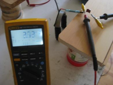
Now that I had low voltage DC, I could make current measurements more
reliably, provided there's enough current to measure. As it turns out,
there wasn't much current. I first used my digital
multimeter (left photo
below) and the current fluctuated between around 6 microamps and 0.5microamps.
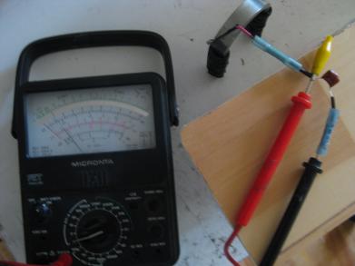
I then tried measuring the DC voltage using my analog meter (right photo below)
and was barely able to get 0.1 volts DC. This was likely because the low
current wasn't enough to move the meter coil sufficiently.
Converting the Van de Graaff machine spikes to low voltage directly
The final test was to see if I could convert the high voltage spikes from
the Van de Graaff machine to low voltage DC directly. The photos below
show that this works.