The objective of this experiment was to test the theory that the testatika
pots are really capacitors and if a DC voltage could be gotten from them.
One result, as is detailed below,
is that there was a DC voltage but only because of leakage current at one
electrode. When the leakage current was fixed, the DC voltage disappeared.
The output power was around 21milliwatts. Could the testatika's pots be
leaky capacitors? Another perhaps more useful finding
was that the small 2V peak-to-peak AC that was riding on the DC HV input was
amplified about 16 times to around 32V AC on output. It's uncertain yet if
the amplification was also driven by some leakage current.
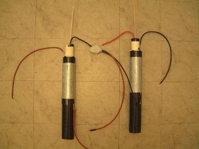
The Capacitors
Each capacitor consists of 2 electrodes (an inner one and an outer one)
plus a center grid. Following in the picture below from left to right is:
the inner electrode consisting of 10 AWG insulated wire formed into a
coil, the center grid for getting output, and the outer electrode which is
also a grid. The grids are aluminum. The inner electrode slides into the
biege PVC cylinder which has the center grid wrapped around it. This in
turn slides into the black ABS cylinder which has the outer electrode wrapped
around it. Once assembled you have the completed capacitor as shown on the
right of the equal sign.
The two capacitors connected together by the
wires that will be connected to the HV side. Note that for the one on the
left that is the center electrode and for the one on the right that is
the outer electrode (the redish/orangish wire coming from the inner electrode
of the capacitor on the right is not connected to these, its end is just
sitting close by).
 |
|
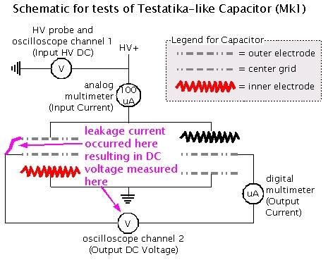
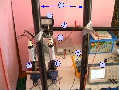
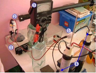
The Experiment Setup
(1) ABS (plastic) poles for attaching things,
(2) 24V supply
for HV 30kV supply (hidden, see next picture),
(3) HV probe
for measuring input voltage (see next picture for more),
(4) oscilloscope for displaying input voltage and output voltage,
(5) meter for measuring input current (caused by leakage),
(6) meter for measuring output current,
(7) and (8) capacitors.
 |
|
(1)
HV 30kV power supply (gets input from 24V supply),
(2) HV probe tip touching output of HV 30kV supply,
(3) meter for measuring input current (caused by leakage),
(4) HV input connections to capacitors, notice they are different for
each capacitor (more in next two pictures),
(5) HV three wire connection covered in wax to minimize leakage.
 |
|
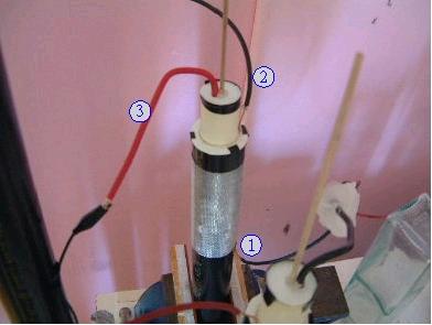
(1) HV goes to outer electrode,
(2) connection to center grid for output,
(3) ground goes to center electrode.
 |
|
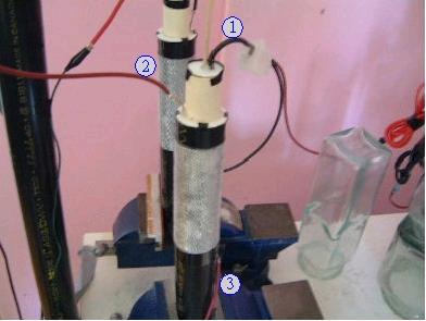
(1) HV goes to center electrode,
(2) connection to center grid for output,
(3) ground goes to outer electrode
 |
|
The Results
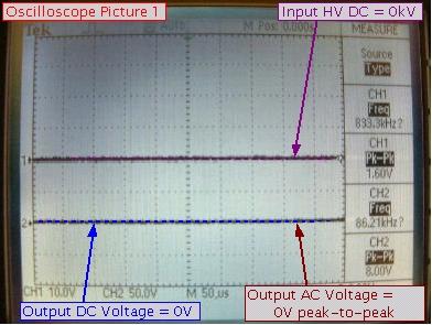
The tests were done by simply turning up the high voltage while writing
down current readings and snapping pictures of the oscilloscope output.
The following are the results summarized and below that are the oscilloscope
pictures.
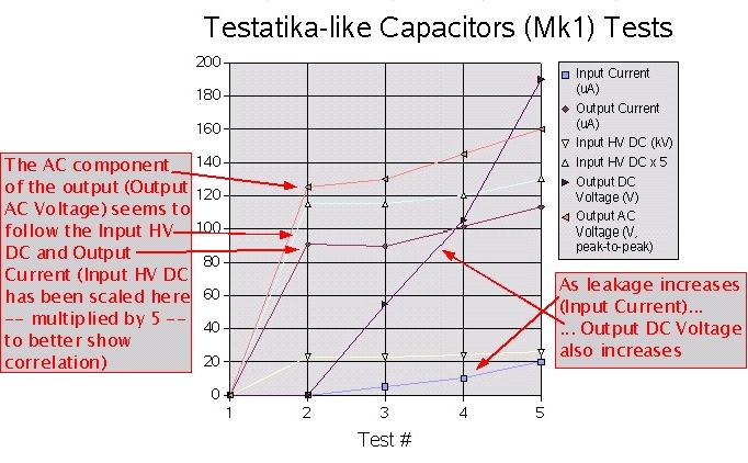
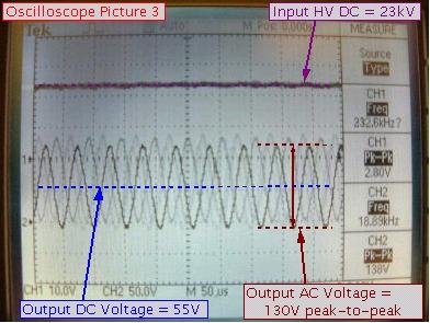
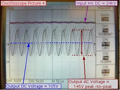
The DC component
One interesting thing that was found was that there was a large DC voltage
measured across the center grids. As the high voltage was turned
up, the input current increased though the measured input voltage stayed
fairly flat. This makes sense as the leakage would hamper the voltage from
rising. The input current was due to leakage at one capacitor between
the connection to the center grid and the top edge of the outer grid
(details below).
The leakage is what resulted in the DC output and is what kept the
measured input voltage down.
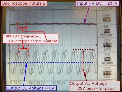
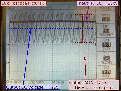
The AC component
The other interesting thing that was found was that there was a large AC
amplified component riding on the DC one. The AC on output was due to
ripple in the input voltage, known to be the case because they had the
same frequency. The AC ripple on input was only about 2 volts peak-to-peak.
The AC voltage on output was as much as 160 volts. However, when the leakage
current was eliminated (as much as it could be) the AC voltage on output
was only 32 volts (see very bottom). It's possible that this was due to
there still being some leakage current. More experimenting is needed
as the significance of this AC component was not thought about until
a few weeks after the tests.
The Data
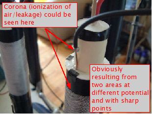
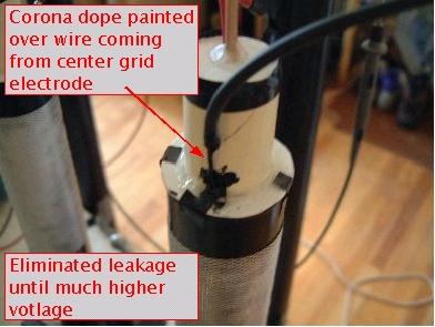
Leakage Details and Fixing
The following shows where the leakage was coming from. This resulted in the
input current. This input current is what held this center grid at
a different voltage than the center grid in the other capacitor and
is why an output DC voltage was measured.
I fixed the above leakage by putting corona dope on the wire coming from
the center grid as is shown in the following picture.
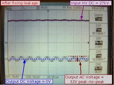
The result was that I could now turn the high voltage much higher without
any output DC at all. This means that there was no longer a potential
between the center grids except for the AC component. Note that the
AC component is less but still present, possibly due to there still
being some small leakage current. The following oscilloscope picture shows
this.