The Hyde generator is a device developed by William W. Hyde that puts out
more energy than is used to run it (to me this means it must tap into some
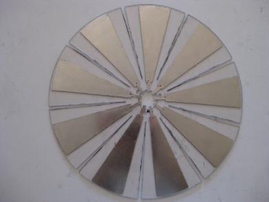
unexpected energy source.) It's basically a large high
voltage capacitor with spinning rotor segments actually in between the
capacitor plates, chopping the electric field at high speed (> 6000 RPM.)
Stator segments
are also in between the capacitor plates and it is actually the electric
field between the stator segments and the capacitor plates that is chopped.
The resulting output energy is taken off of the stator plates using
capacitor/diode networks.
In his book, Moray also states "when the rotor is spun on the order of
6000 rpm, a 3 KV potential across the excitor plates yields stator
pulses in excess of 300 KV with a very small drag on the rotor." It
was these unexpected pulses that Hyde noticed and then empirically
derived his circuit for to step down at the output.
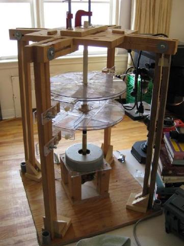
My 1st attempt was with a vacuum cleaner motor at one end and an 18"
long shaft with everything attached. The long shaft made it too unstable
at high speed. The best I could safely do was around 2700 RPM.
My 2nd replication attempt
I first finished all parts for my 2nd attempt, assembled it and ran it
for the first time on
April 7, 2009. By April 23, 2009 I'd found I was unable to get the
motor to spin the disks faster than 4000 RPM. The motor is rated at
10,000 RPM no-load and can do that with featureless disks but can
do only 4000 RPM with the completed disks. My guess is the disks
with their radially cut slots and metal segments attached act like
fans and the air load is too high.
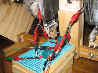
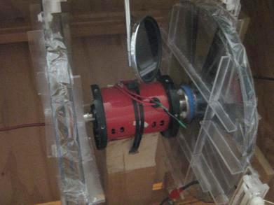
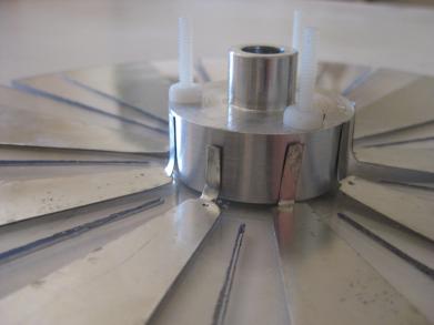
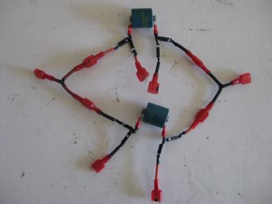
Closeup.
Output wiring from the stators. One pair of stator segments so far.
March 23, 2009 - First speed test
April 7, 2009 - First run after completing all parts
The construction details are below, following these updates.
At the suggestion of Paul on
overunity.com
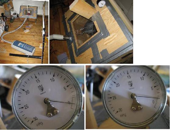
I sealed the box and lowered the pressure with a household vacuum cleaner motor.
I managed to drop the pressure by about 0.5 PSI ( around 1 inch Hg). I didn't
see any improvement in RPM, the best being around 3900 RPM, so I would have to
drop the air pressure even more. The outer acrylic window was seriously bowed
inward so I don't think I'd want to do further improved sealing without replacing the
window with a solid board. I'd also be afraid of going further out of fear of
damaging my vacuum cleaner. It was worth a try though.
May 5, 2009 - Sealed edges with packing tape - 4500 RPM!
I guessed that maybe if I sealed the area where each rotor is, once the air gets
moving, since it's enclosed in a circular pathway, it will keep most of its momentum
and act like less of a load and I'd be picking up less new dead air. Plus, in the patent the rotors are sealed in a circular
housing in the same manner. I got 4500 RPM, an encouraging improvement.
I used clear packing tape so I wonder if I used something less crinkly if it would be
even better. Still no HV spikes, but Hyde didn't get those until around 6000 RPM.
May 19, 2009 - Higher input voltage, sealed rest of housing, and a bang! - 5200 RPM!
At Luc's suggestion I decided to run it with higher than the motor's rated
input voltage of 110VAC, something I was previously reluctant to do but as
Luc said "I was so close to the 6000 RPM". Luc pointed out to me how to get
2 phases out of my wall sockets to get up to 220VAC and even more using
variacs (which I didn't realize variacs would do), but for starters I tried
it with just one variac at its maximum output of 130VAC. I got 4660 RPM! My
previous best at 4500 RPM at 110VAC so it looks like I'd get around 80 RPM
for each 10VAC I add; not much.
Then I decided that since I had big success on May 5 (reported above) with
sealing just the area where the rotors were and since at 4660 RPM it was screaming
like a banshee from the air coming out of the holes in the wooden box, I should
seal the area where the motor was too, just as is done in the patent.
Success, I got 5200 RPM! Only 800 RPM to go.
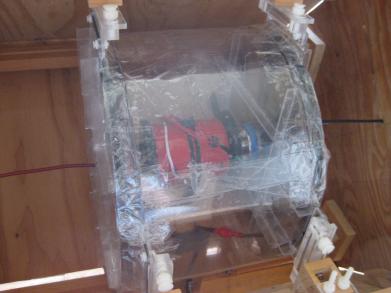
Fully sealed using a thin acrylic sheet and packing tape.
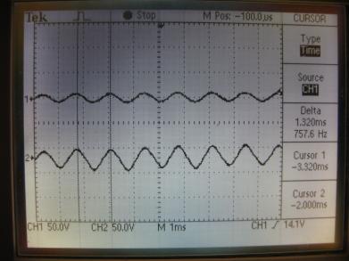
Here are some scope shots. The AC is expected and normal. It's HV
spikes that I'm after but at no speed or voltage did I see any. The 757Hz from
the scope shot below is per segment, not per rotation of the entire rotor. There
are 9 segments per rotor so to get RPM take the 757Hz and divide by 9 to get
rotations per second for the whole rotor. Then multiply by 60 to get rotations per
minute (RPM), 5046 RPM. However, I did get 5200 RPM at one point, just no photo of
the scope at the time. The voltage was set to 3kV when it was at 5200 RPM, the same
voltage Hyde was using when he was doing 2kW in and getting 20kW out.
Scope shot with 3kV.
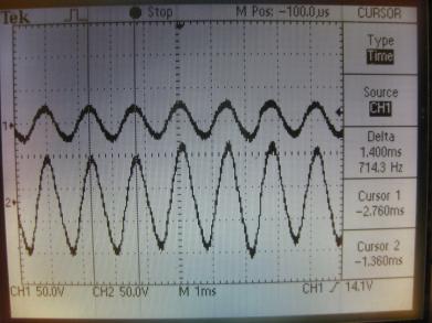
Scope shot with 10kV.
And then there was a muffled bang and the whole box began to slowly slide across
the floor. One of the segments had come off a rotor (the bang) and this unbalanced
the whole thing (the slow sliding.) The only damage was a hole in the packing
tape where the segment flew out from between the rotor/stator area and the
mangled segment from when it hit the inside of the box in an awkward area which
caused it to bounce around.
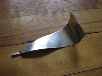
The segment that flew.
Construction details for 2nd replication attempt
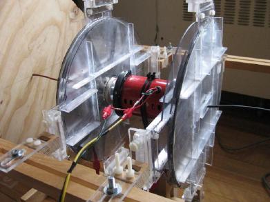
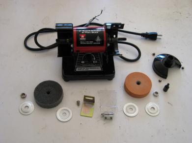
The motor came from this Neiko Tools USA 3" mini bench
grinder I bought off of ebay. It uses 110VAC and is rated 10,000RPM no-load.
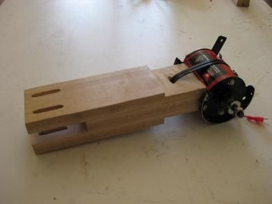
I modified it and mounted it on a hardwood arm. I originally
had an aluminium arm but switched to hardwood in hopes of minimizing any effect
on the generator's HV electric field.
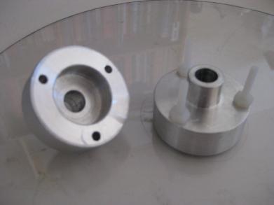
The aluminium disk hubs were machined by a local machine shop.
Note the slots cut radially in the disk. Note also the
way the metal segments have tabs sticking out over the center hole.
The tabs from the metal segments are bent up to meet
the side of the hub...
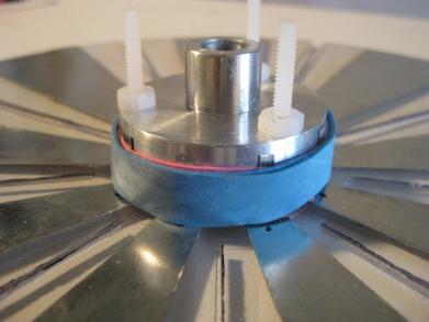
... and are pressed against the hub using elastic rubber bands.
This is to get conductivity from segments to hub to motor shaft to the other
disk's hub and segments. This is different than the patent but was an improvement
that Hyde made and told to Moray King1.
The stator plates. At this time I had only one set of
segments for capturing the hoped-for high voltage pulses.
This is capacitor/diode network as per the patent. I'm
using high voltage diodes and doorknob capacitors.
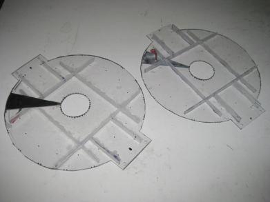
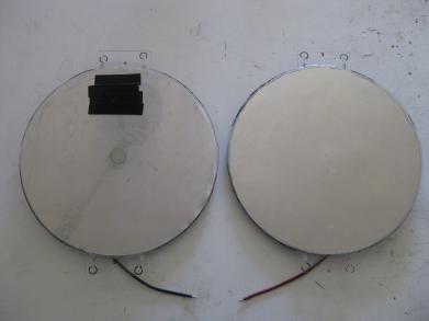
The high voltage capacitor plates that go on either
end of the generator and are connected to the HV power supply. Note that
the metal disk for the negative plate (left plate in photos) is
behind the plastic as per the patent. There was a hole in the middle of
the plastic so I filled it with epoxy. The black tape is a background for
the phototachometer.
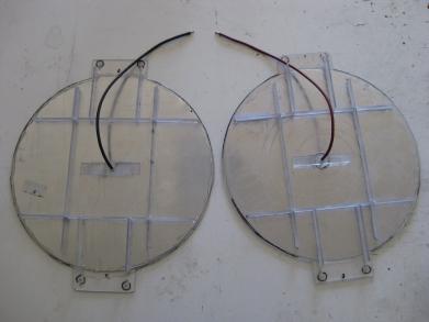
Back or outside facing sides of the high voltage capacitor
plates. Since the metal disks are aluminium I had to use pressure to attach
the wires (i.e. I couldn't solder.)
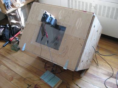
The whole thing was boxed up in case something flew off.
The phototachometer is attached. A mirror inside redirects the phototachometer's
light onto the disk.
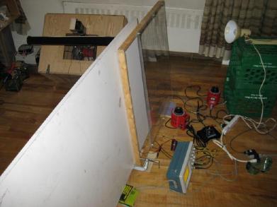
For additional safety I errected a further barrier.
References
1. King, Moray B. Quest for Zero Point Energy. Adventures Unlimited Press, 2001,
p. 28