LC circuit (aka tank or resonant circuit)
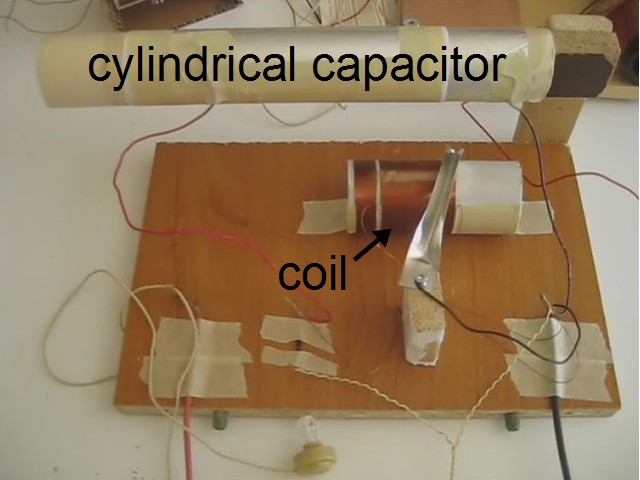
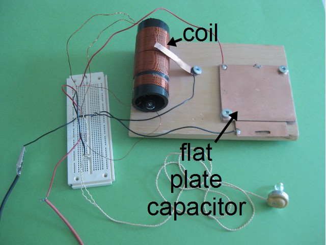
An LC circuit is one consisting of a coil and a capacitor that resonate with each other, passing energy back and forth between them (a circuit is shown below). This happens at a specific frequency, called the resonant frequency. The L is the symbol for inductance, which is a property of the coil. The C is the symbol for capacitance, which is a property of the capacitor. The examples in the photos below show crystal radios each with their coil and capacitor connected in parallel.
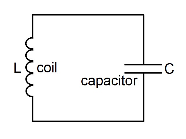
LC circuits are used for a number of things such as generating signals at the resonant frequency and for picking out a specific frequency (the resonant frequency) from a circuit with many frequencies. Picking out a specific frequency is what's going on in a crystal radio where the coil and capacitor are connected in parallel.
In reality, resistance also plays a part, but often when doing the calculations we ignore the resistance. When including resistance, we talk about an RLC circuit instead, the R representing the resistance.
How an LC circuit works
The coil's inductance (L) and the capacitor's capacitance (C) are selected such that they resonate as a specific frequency. A formula is given the a section below showing how. As shown in the animation, they exchange energy back and forth at this frequency. During the time when current is running through the coil, either increasing or decreasing, a magnetic field is created around it. While the current is increasing, the magnetic field grows in strength. While the current is decreasing, the magnetic field weakens. When there is no more current, there is no more magnetic field. The capacitor is doing the opposite with respect to the current. While the current is increasing, the capacitor is discharging. While the current is decreasing, the capacitor is charging. When there is no more current, the capacitor is fully charged.
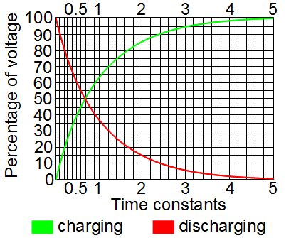
This all makes sense. If current was still flowing then the capacitor wouldn't be fully charged -- its charge would be changing. But once it's charged, there's nothing keeping it charged and so that charge circulates back through the circuit, providing the current. A capacitor doesn't discharge at a constant rate (see the graph). It starts discharging slowly and rapidly speeds up, meaning the current also starts slowly and rapidly speeds up. Current moving through a coil creates a magnetic field, and so while the capacitor is discharging, the magnetic field grows in strength. But when there's no more charge on the capacitor, there's no more current, and so the magnetic field collapses. A changing magnetic field induces current to flow in a circuit, and while the field is collapsing, it is changing. And so current flows in the circuit. That current charges up the capacitor again and we start over.
LC resonant frequency calculator, and variations
Here's a calculator for working out the resonant frequency. The formulas are below in case you're interested.
However, sometimes you know the frequency you want and either don't know that capacitance or the inductance you need to get that frequency. So below are calculators for those two instead.
Calculating the LC resonant frequency
The formula you need for calculating the resonant frequency of a parallel LC circuit is as follows:
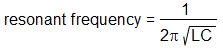
The L in the above resonant frequency formula is the inductance of the coil. If you don't know the inductance than you can calculate it using the online calculator or the formula on this page about coil design and induction.
The C in the above resonant frequency formula is the capacitance of the capacitor. It's difficult to give a formula for this since there are many shapes for capacitors and each have different formulas, but you can find online calculators and formulas for a few of them on this page about capacitance.
Video - LC Circuit (Parallel): Selecting Coil and Capacitor
This video shows the coil's magnetic field and the capacitors's charge in action, explaining it all. It also goes through an example of using the formulas and calculators for selecting the inductance and capacitance in order to get a desired range of resonant frequencies for the LC circuit. The example used is of a crystal radio.
