Joule thief circuit powering a clock
Those who make joule thief
circuits under that name usually use them to power an LED or CFL
but with some additions Lionel Sear
( )
has made it power a clock. The following is his detailed write-up.
Thanks to Lionel for sharing this.
)
has made it power a clock. The following is his detailed write-up.
Thanks to Lionel for sharing this.
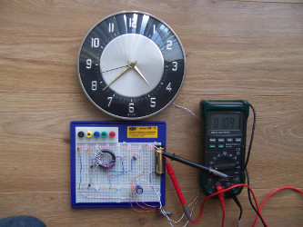
It has been found possible to power a conventional battery electric clock of the type produced in many millions. This type of electromechanical clock typically draws a short current pulse of 10 to 20 milliamps each second and our circuit is able to satisfy this surge from the large bucket capacitor. In this application the circuit draws a steady 1 or 2 milliamps from the supply battery at 0.7 volt and can operate with a battery down to 0.5 volt. The clock application is perfect for the circuit.
The circuit is not able to output much in the way of current, which will limit its use. What it can do is to charge up quite large capacitors to a controlled voltage and charging up super capacitors is a definite possibilty.
The following is a video with many details and of it in action.
The circuit
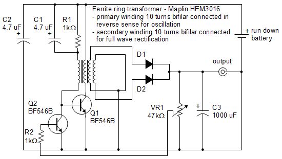
Transistor Q1, resistor R1 and electrolytic capacitor C1 together with the leftmost two windings of the ferrite ring transformer form a conventional Joule Thief circuit which has been reproduced many times in many places. C2 decouples the supply line which is always good electronic housekeeping but is extra important in this case as the oscillator waveform is extremely rich in harmonics which can radiate within and outside of the circuitry. The usual LED is not included in the final circuit but see below. This circuit has some additional components which enable us to extract power from the oscillator toroid and then rectify and control it. The oscillator toroid has two further windings which are wired as a centre tapped secondary connected to silicon diodes D1 and D2 to form a conventional full wave rectifier giving a positive voltage across VR1 and C3. The wiper of VR1 is connected back to the base of Q2 via R2. When VR1 wiper voltage exceeds the base threshold voltage of Q2, (circa 0.5 volt,) this transistor is turned on which loads the base of the oscillator transistor Q1 turning the oscillator down. This crude control is adequate for many applications and certainly for powering a battery clock. Note that the toroid oscillator windings and the secondary windings are bifilar wound.
Tips for making it
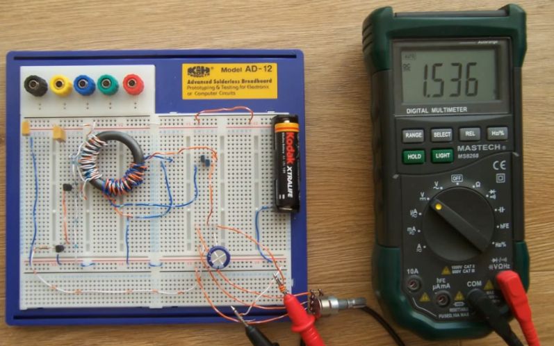
You may find it helpful to construct the circuit in stages. The simple Joule Thief oscillator part of the circuit can be assembled first with the usual LED to provide reassurance that the oscillator is running. The oscillator transformer secondary winding can then be brought in and connected to the two diodes loaded with a 22 kilohm resistor and a 4.7 uF electrolytic capacitor to show that a DC voltage is being produced. In this example the circuit produces an unregulated 4 to 6 volts depending on the level of the supply battery. Now the 22 kilohm resistor can be replaced with the potentiometer and the wiper taken back to the base of Q2 and you should be able to control the output with the potentiometer. Once you are able to regulate this to, say, 1.4 volts you can add the 1000 uF bucket capacitor and then your clock simply connected between the output and battery negative. For maximum efficiency the LED can probably be omitted in the final stages or at least used with a ballast resistor that keeps it dim.
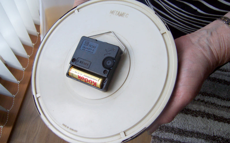
As shown below, the wires make contact in back of the clock where the clock's own battery would normally go. Each end is held in place by inserting a wooden dowel where the battery would normally go.
Future work
The author is now looking into making home made batteries to run clocks for long periods. Another possibility is using a very small solar cell array to power the circuit which charges a super capacitor to run the clock through the hours of darkness.
Other joule thief stuff

|
Do you have a project you'd like to share on rimstar.org too? You're more than welcome to. Click here for details. |
|

