Solar Pool Heating - Control and Automation
Manual versus automatic control
The control valve can be either a manual one or an automatic one. With a manual control valve, if you want the pool water to be heated up and the sun is out, then you'll have to turn the handle on the valve yourself to get the water to flow to the solar collectors. Then, at night, you'll have to manually turn the handle again to stop the water from flowing to the collectors otherwise your hot pool water will flow through the now cool collectors, give its heat to the collectors and then go back into the pool as now cooler water.
Automatic control
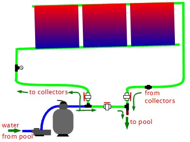
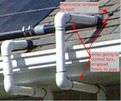
An automatic control valve with a control box and two temperature sensors (also called thermistors) handles all the above for you. The control box contains a differential temperature controller which makes decisions based on input from the two temperature sensors. The diagram and photo below illustrate these components. One temperature sensor is on the roof, positioned where it will get sun whenever the collectors are getting sun and be shaded whenever the collectors are shaded. The other temperature sensor monitors the temperature of the pool water by being inserted into a pipe that contains water coming from the pool. The automatic control valve has a motor to open and close the valve. The control box monitors the temperature sensors and controls the valve's motor. It has a switch and a dial on it. The switch normally has three positions: turn on the automatic control system, turn it off, and do a test. The dial lets you tell the system what temperature you want the pool water to be.
If the temperature of the pool is cooler than what you selected via the dial then the control box will use the temperature sensor near the collectors to determine if allowing water to flow through the collectors will heat the water up. If the sky is cloudy then the temperature sensor will be cool and the control box would do nothing. However, if the sun is out then the temperature sensor will be hot and the control box will turn the control valve to let water flow through the collectors.
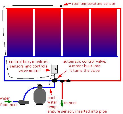
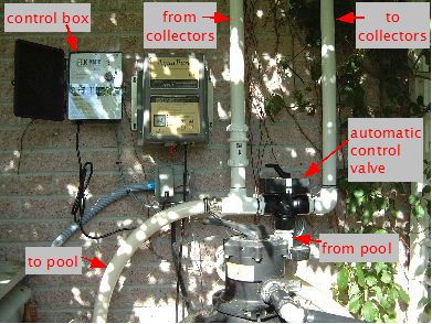
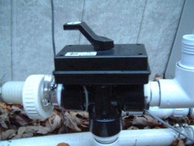
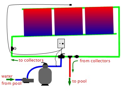
Automatic control systems or "solar control kits" consist of four components: the temperature sensors, the control box, a 3-way valve, and a motorized actuator. The motorized actuator turns the valve when the control box tells it to. In the photo above you can see the motorized actuator firmly attached to the top of the 3-way valve.
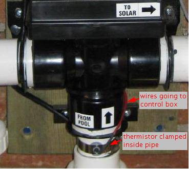
For the pool temperature sensor, a hole is drilled in the pipe coming from the pool filter before it gets to the control valve. The temperature sensor, a thermistor, is inserted into the hole so that it will be in contact with the water from the pool while it is still at the pool's temperature. An o-ring prevents leaks. The sensor is clamped firmly into place using a hose clamp.
For the roof temperature sensor, also a thermistor, a wire is run up to the roof to a location that gets the same amount of sun as the collectors. The sensor is connected to the wire and then screwed to the roof.
Also, see the section below on where not to put a chlorinator if you're going to use this type of plumbing arrangement.
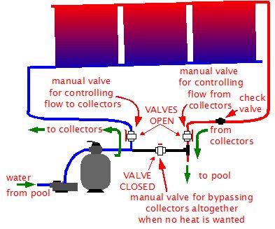
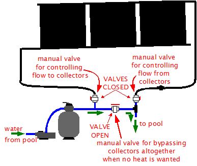
Manual control using three valves
The main solar pool heating page aleady showed a diagram of a manual system using a single control valve and a check valve. The following two diagrams illustrate how a manual system can be done using three identical manual valves. Two valves control the flow to and from the solar collectors and one allows for bypassing the collectors if there is no heat available or it is available but not wanted.
Also, see the section below on where not to put a chlorinator if you're going to use this type of plumbing arrangement.
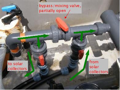
Controlling pressure/flow rate and temperature using a bypass/mixing valve
Besides being used to bypass the collectors, the bypass valve illustrated in the above diagrams can also be used for two other purposes: to control the pressure/flow rate of the water in the pipes and collectors in the solar part of the system; to control the water temperature in a manual system.
This is done by opening the bypass valve only part of the way, causing some water to still go to the solar collectors and some water to bypass the collectors. The following diagram illustrates this.
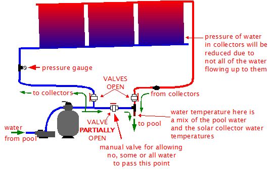
To control pressure and flow rate you turn the valve part of the way, allowing some of the water to flow up to the collectors and the remainder to bypass the collectors. A pressure gauge can be installed inline with the piping as shown in the above diagram. Controlling pressure can be important in systems where the pool pump is a very powerful one such as 2 or 3 horsepower. This may produce too much pressure for the collectors, eventually causing damage to them.
To control temperature you turn the valve part of the way, the same as you do for controlling pressure. This causes only some of the water to go up to the collectors and be heated. Once the heated water comes back from the collectors it then mixes with some of the cooler water that bypassed the collectors resulting in a temperature that is a mix of the two. When being used for this purpose the bypass valve is also called a mixing valve.
Also, see the section below on where not to put a chlorinator if you're going to use this type of plumbing arrangement.
Where not to put a chlorinator
Some things, like a chlorinator, should always be functioning while the pool pump is on (unless you are using an entirely separate pump for the solar pool heating system.) Don't put those things in the section of pipe that has the bypass valve or on the pipes going to/from the solar pool heating collectors since they will want a normal flow of water. The following diagram shows these pipes that should be avoided in green.